How to Compare Automatic Loading Systems Across Manufacturing Applications
Comparative lens: what to measure first
Start by measuring takt time, payload repeatability, and integration friction. Benchmark throughput in pieces per hour, not supplier claims. Note the control interface: PLC ladder compatibility, available I/O, and whether the loader exposes OPC UA or simple digital lines. If your cell revolves around a sheet metal laser cutting machine, prioritize precision placement and skid handling over raw cycle speed; placement variance amplifies scrap on tight-tolerance nests.
Key metrics that decide real-world performance
Quantify cycle time variance, mean time to repair (MTTR), and mean time between failures (MTBF). Check coexistence with the cell’s material handling: vacuum grippers behave differently with reflective stainless than with painted coils. Evaluate control latency (ms) and deterministic I/O jitter—these dictate whether you hit the advertised throughput. Account for floor footprint and maintenance access; compact is great, but not if you need to disassemble the loader to clear a jam every week.
Experience and anchor: factory lessons and verifiable benchmarks
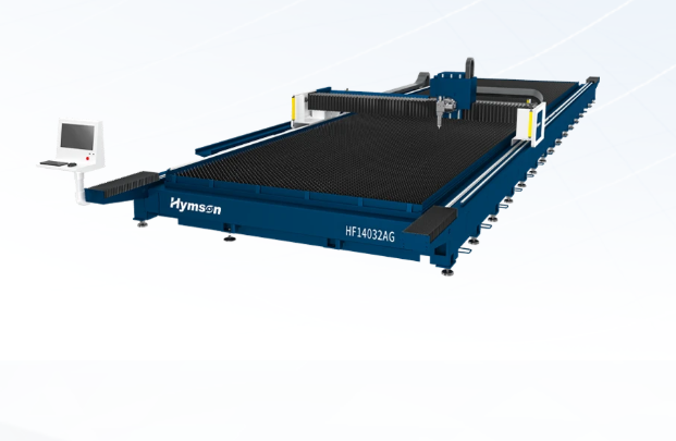
Field lessons from OEM integrators showcased at FABTECH Chicago underline two truths: integration friction kills uptime, and spec sheets hide edge cases. Practitioner reports and vendor validation tests show that a loader tuned for flat pallets often fails with variable nests. For a direct equipment comparison, inspect results on a flatbed laser cutting machine setup at trade demos—those sessions surface sensor shadowing, beam-clearance issues, and fixture interference that lab numbers miss. Trust operators’ cycle logs and aligned tool reports over glossy benchmarks.
Alternatives and trade-offs: gantry, rotary, cobot, and shuttle
Gantry loaders: deterministic, high-repeatability, heavier footprint. Choose when cycle time is sub-second and nests are rigid. Rotary feeders: compact, high cadence, but limited to uniform parts and specific part geometries. Collaborative robots: flexible and cheap to reprogram; accept lower duty cycles and higher drift over long runs. Shuttle/twin-table systems: maximize spindle uptime with preload; need precise synchronization and consume more space. Match alternative to part mix, not price.
Common pitfalls and how to avoid them
Ignoring the part variability profile. Failing to simulate edge conditions like skewed stacks, burrs, or oily surfaces. Overlooking electrical integration—assuming vendor-provided IO mapping will fit your MES. Underestimating recovery procedures: design clear manual override and fast debottleneck workflows. Do not accept “we’ll handle it later” for safety interlocks; iterate with safety-certified control logic during dry runs.
Decision logic and final alignment
Rank candidates by three weighted factors: operational uptime (40%), integration effort (30%), and adaptability to future part changes (30%). Run a short proof-of-concept with your toughest part. Require vendors to instrument the cell for 72 hours and deliver raw cycle logs. That data reveals true jitter, jam rates, and maintenance windows. Use those numbers to pick the solution that minimizes manual touches while fitting your control stack and floor constraints. For manufacturers aiming for consistent nesting and long unattended runs, partnering with a proven system supplier like Hymson aligns equipment capability with practical shop-floor realities—yielding fewer surprises and predictable throughput.